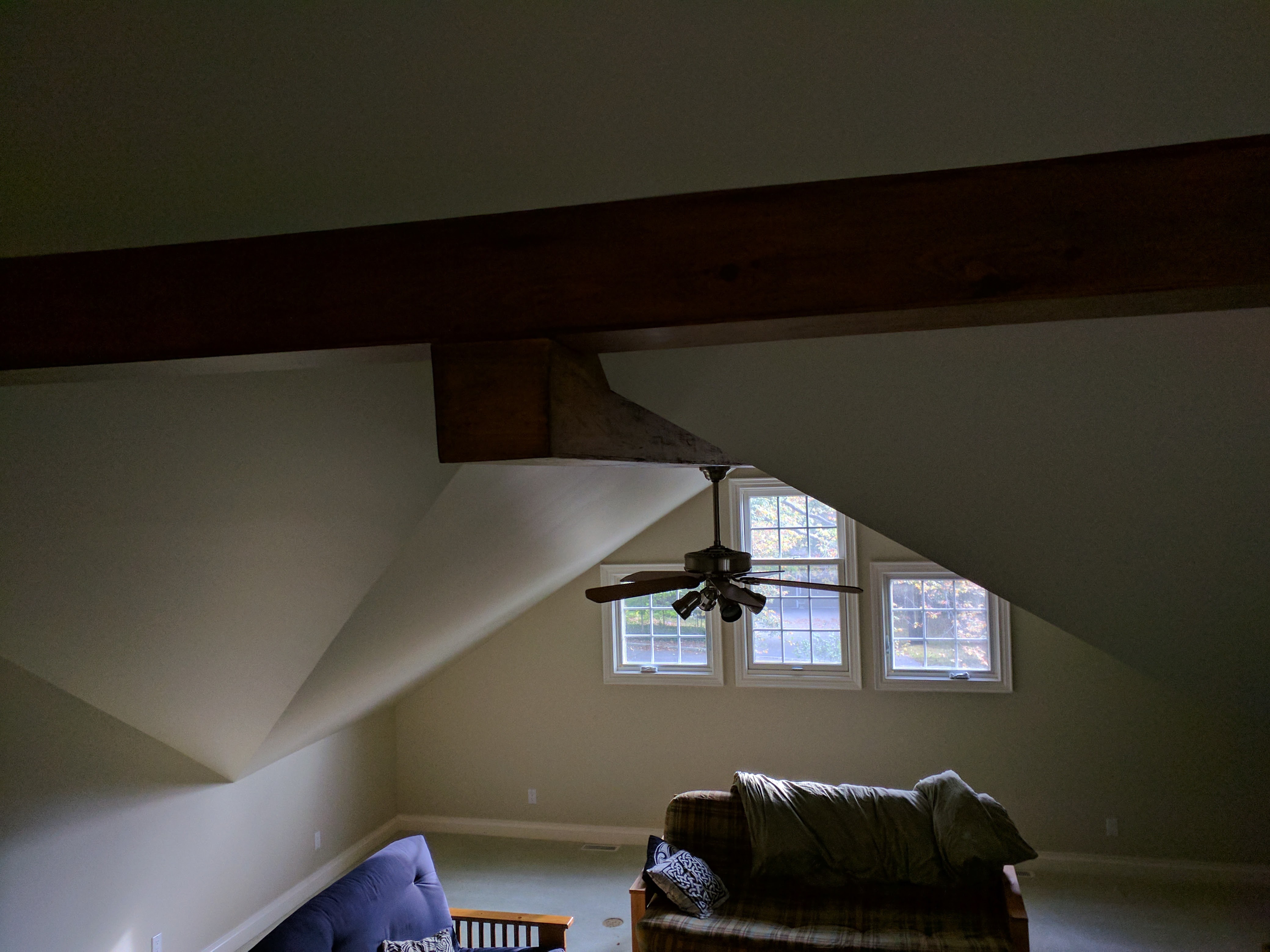
 So here @ casa don there are two big ceiling fans. Casablanca Panama II 6645T models, each with a light kit. You can see what it looks like in the wild on the right.
Now, sadly, both have become ill. The one directly over my desk works ok, but after a few minutes the fan starts making a buzzing electrical noise.
The one in the photo, well, not so much action.
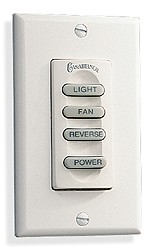 But even without these problems, there is a more basic one… The ‘smarts’ are some 80’s era X10 style, with a wall-switch like this one. It operates wirelessly (I think using X10-style zero-crossing rather than radio). And this is nearly 2020, we should be able to run duke nukem 3d on a fan by now. Or at least crysis.
OK, so step one, ladder, screw driver, hex driver, dust removal (eww), and we are in. There is a control board sort of around the fan. There are 6 triacs (and 6 speeds…. hmmm… coincidence?), and a ‘resistor pack’ strapped down the side.
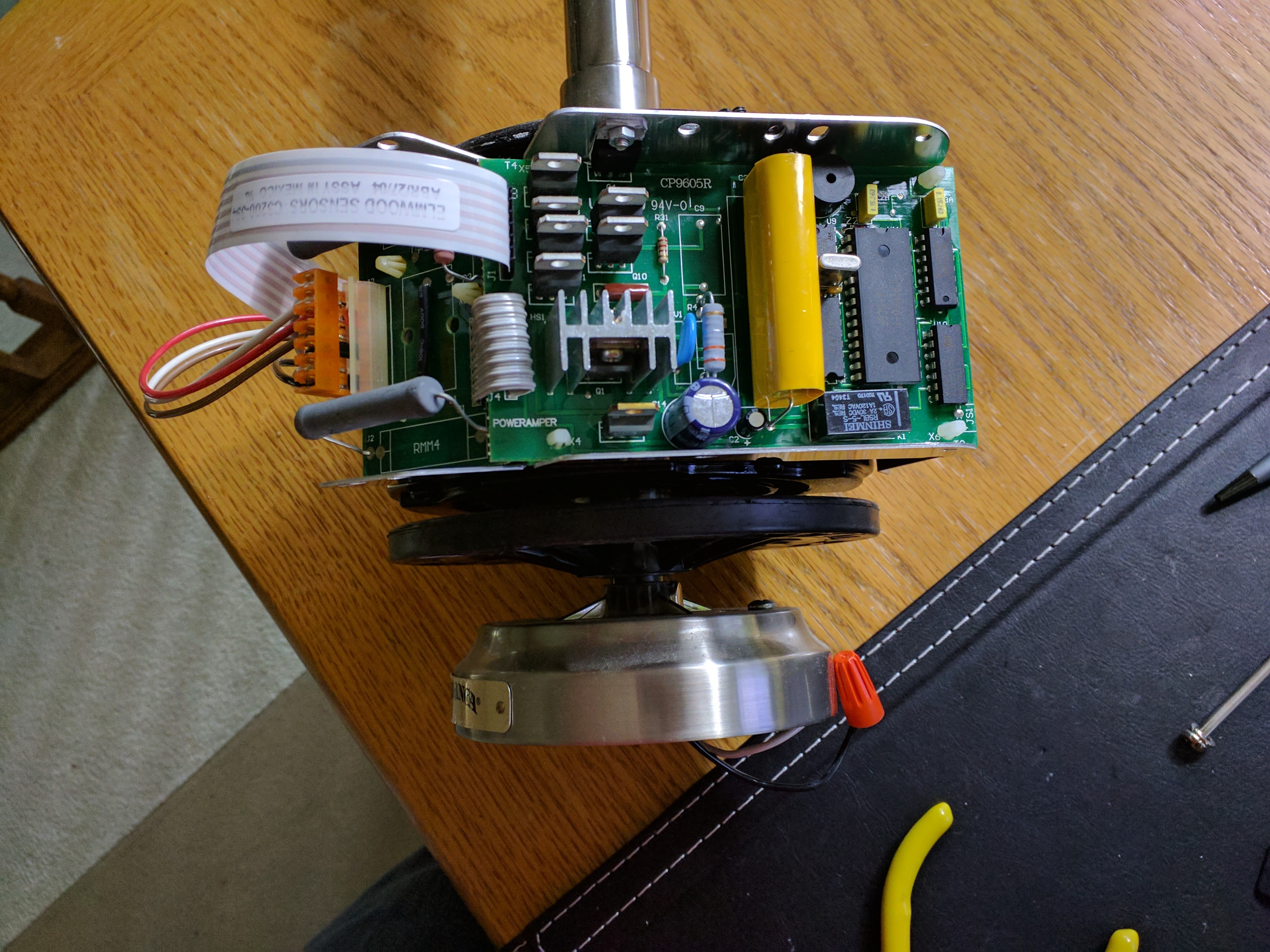
If we look in a bit more detail, there is a relay (DPDT) which I’m pretty sure is for the reverse. There is a 10uF capacitor which runs to one winding of the motor, and then the AC runs to the other winding through that resistor pack/triac setup.
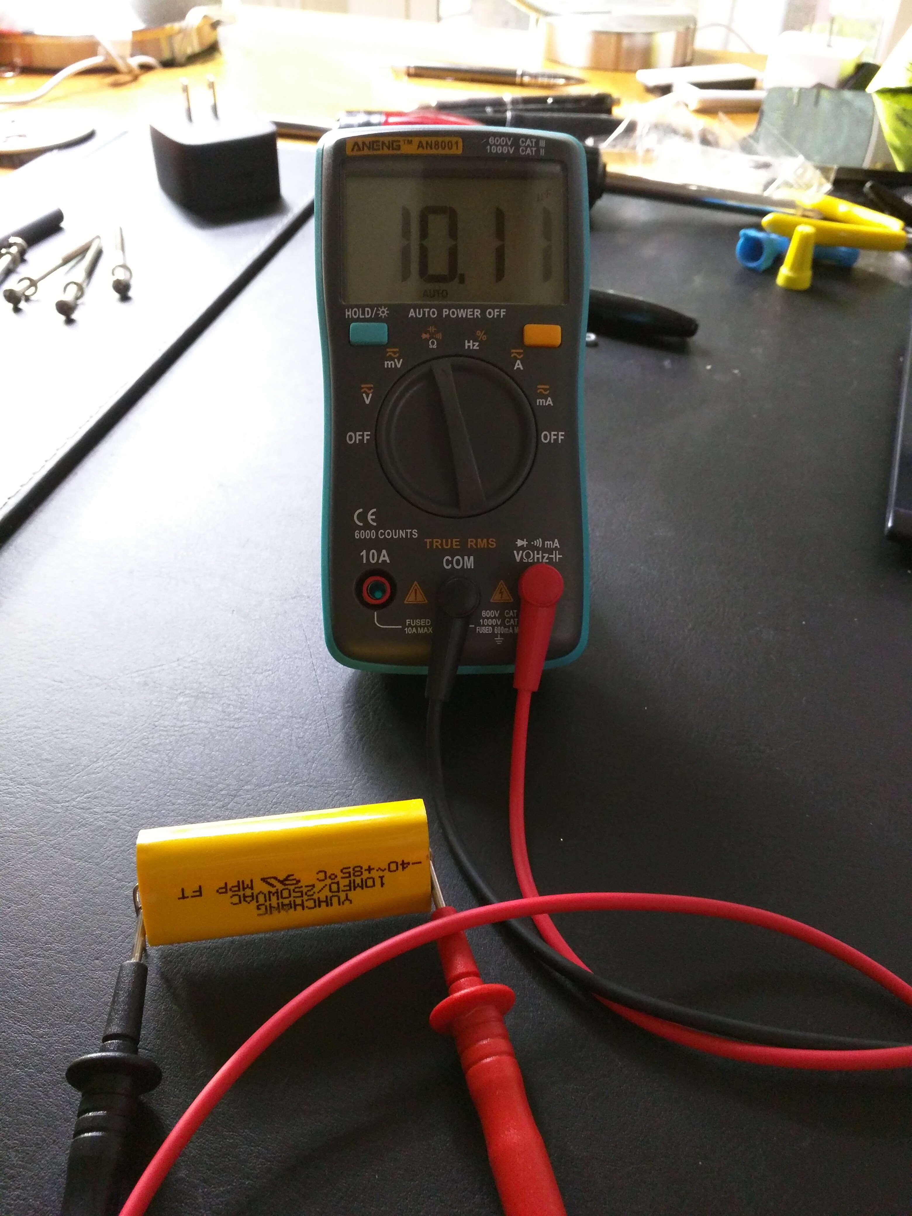 Now, the most likely culprit for the noise is the capacitor. Capacitors fail over time, particularly when they are from ‘2nd tier’ brands, as this one is. So i remove it and check with the meter. Interesting, the Yuchang 10mfd/250wvac shows 10.11 uF. But my meter doesn’t measure ESR. Hmm. OK, i’m going to order two replacements from digikey. I picked the MMP2W10K-F, I hope its a decent match, i couldn’t find a a datasheet on the Yuhchang site, this was the closest.
OK, so step one will be to see if the capacitor swap fixes the noise. But step two clearly has to be to get an IP address on this thing.
So here’s where it breaks down as method. Method A, i do some retrofit. I add an ESP8266 to this circuit board. I have the ESP drive the same TRIAC (and sort out what the other switching transistors do, maybe related to the light-kit dimmer?). Method B, i ditch this circuit board, and get some logic-level triac to do the dimmer for the lights, switching to the existing resistor array for the fan (and keep the concept of the phase-shift capacitor/direction-relay as-is).
So… pro & con. If i go with the retrofit model, I get to keep the wall controls and have them coexist with the home automation/voice. If I go all new, well, i’ll understand it all. What should I do gentle reader?
Oh yeah, and given the phase-shift capacitor checked out on the meter, what would you suggest if the buzzing/shorting noise persists after I swap it?
Leave a Reply