Earlier I wrote about the 3rd gen heated handlegrips. I used a “12V” battery box which as 3S2P 18650-based. Sadly it turned out to not really have a BMS inside, and, well, the batteries died permanently. Undaunted I installed a backup set and… the bike was stolen. So, gen 4. Let’s go.
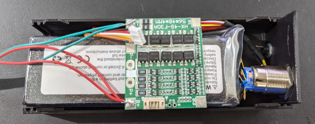
For gen 4 we are taking a bit of a different approach to the energy source. I’ve got a 7000mAH 4S LiPo pouch battery.. Its meant for some remote controlled vehicle. At full voltage it is 16.8V, at nominal it is 14.8. I am going to couple this with a proper 4S BMS with balance leads.
Now, I considered a 12V constant-current/constant-voltage output buckl converter on the output. This would provide the handle bar grips a 12V supply until the battery got near empty, then dropping to 11.2V. Instead, on observing the BMS has about 1 diode drop in normal use, so the output of the BMS is more like 15V at fullish charge, and 11-14V in normal operation. This is sufficiently close to the alternator output of the vehicle these handlegrips were designed for. They have no active electronics, just nichrome wire, so they’ll run warmer when the battery is full, and cooler as it gets close to empty. So I’ll drop the CC/CV buck converter.
This means the wiring is simple: 16.8V charge in to BMS. Battery to BMS. Output from BMS to handle grips.
OK, case time. The 12V battery box had quite a nice robust case, relatively weather proof, velcro-strap to bolt to the bike. I’m going to go with a 3D printed case.

OK, printed. On to the soldering. First we hookup the BMS, have to splice the balance leads, add a deans-t power connector. Boom, measuring @ P1/P2 we have 14.6V for 15.5V out of the battery, so we should be good enough. We’ll lose a bit of voltage in the wires and under load, i should be ok. No fires or shorts! (ps, you have to be super careful with these LiPo, this one can output over 800A (120C @ 7AH). I’ve put a 30A BMS on, the hand grips draw about 4A. In hindsight I should have put a polyfuse in here, let me go rummage for one.
I was considering a trigger to avoid leaving them on by accident and having cold hands on the way home. I might still add this. There is a USB plug on the display on the bike which is switched. I could use its 5V line to drive a mosfet to enable the power. To be continued there I guess.
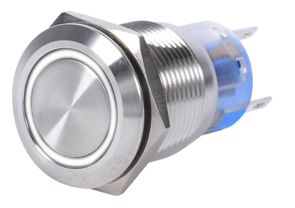
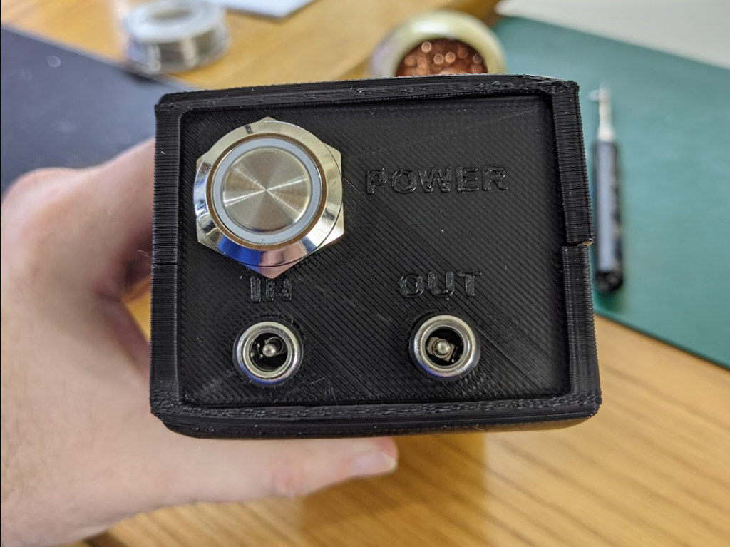
Add a 12V (ish) lighted switch so we can turn it off easily plus know if its on (since the on/off switch of the handlegrips are inside the bear-paws).

Do a quick dry fit of the front-panel, looks good. Time to solder up the wires inside.


OK let’s buckle it up and test. Perfect. We have an output which varies from 11V to 15V, should be ok for the resistive load in these hand warmers. Gen 4 is ready to install!
Leave a Reply